Modern hydronic systems; pitching now more than ever
Elevator speeches.

Image Source: Kenishirotie / iStock / Getty Images Plus via Getty Images
You work in the hydronics industry, right?
So what’s your “elevator speech" when asked to explain what a hydronic heating system does?
Is it bland, such as: You know, there’s a boiler in the basement that burns oil or gas and heats water, and a pump that pushes that water through radiators?
When someone hears your elevator speech describing hydronics technology are they inspired, or do they envision a dirty smelly “box” in the basement (e.g., the boiler), along with old metal pipes and large ugly radiators that collect dust and make weird sounds at times?
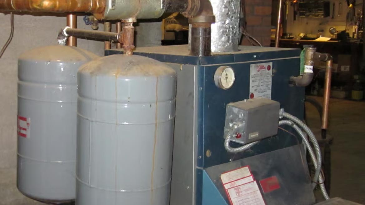
Figure 1 Image courtesy of John Siegenthaler P.E.
Tolerate versus motivate
For decades many homeowner or renters have just accepted that a boiler and radiators are necessary to stay warm in winter. They turn dials or push buttons on a thermostat, hear a click in the basement, and mostly ignore the ticking sounds as hot water races through fin-tube baseboard a few minutes later. They often complain when their fuel bill arrives, but they pay it, and look forward to spring when the whole system can be turned off.
Most people not directly involved in the hydronics industry have little if any appreciation of what a modern hydronic system can do. That’s not meant as a derogatory label of everyone outside our industry. It’s a pragmatic appraisal of the industry’s marginal record of communicating the benefits of modern hydronics technology. That communication task isn’t just for the marketing department at companies that manufacture hydronics hardware. It’s the responsibility of all professionals in the industry from manufacturers, through the sales channels, and especially for those who directly interact with consumers.
Many of those born during or after then 1990s likely consider hot water heating as obsolete. It’s the kind of heating system their parents (or grandparents) had, but no where near as suave as those little white boxes on the wall operated by a remote controller that has more buttons than the one operating their 78” flatscreen. This mindset isn’t just common with many consumers, it’s also held by a good percentage of builders, architects, and government energy planners.
Perhaps that’s why the share of hydronically heated homes in the US remains a small fraction of those heated by forced air.

Figure 2 Image courtesy of nd3000 / iStock / Getty Images Plus
What’s ahead?
Based on what you just read you might be thinking that it’s time to throw in the towel on hydronics, and just pick up a line of ductless mini-split heat pumps.
That’s absolutely not the case!
My assertion is that right now is one of the best times to be involved with modern hydronic systems, - and I’ve been in this industry for over 45 years.
So why the optimism?
Because there’s plenty to be optimistic about… Let’s consider several converging trends that point to the potential for strong market growth.
Work with them
Like them or hate them, government mandates for energy conservation and electrification are rapidly coming into effect. By the end of this decade, if not sooner, these mandates are going to drastically alter the status quo for home energy use. On the bright side, these manipulations of the energy markets can be favorably leveraged by those willing to work within them.
Energy codes, such as those in the 2021 International Residential Code (IRC) published by the International Code Council (ICC), form the basis for many state energy conservation and building codes. Those codes are requiring new homes to have progressively lower heating and cooling loads. The days of a nominal 30 Btu/hr/ft2 as a typical residential design load for new construction are long gone. Today, a 2,300 square foot 2-story home constructed over a fully heated basement, and built to the minimum IRC requirements would have a design heating load of about 11.8 Btu/hr/ft2. That equates to an estimated heat loss of 27,300 Btu/hr when it’s 0 ºF outside. Under more typical winter load conditions that load is probably around 18,000 Btu/hr.
These new loads require new thinking. The smallest gas-fired or oil-fired boilers available would be grossly oversized for the design loads described in the previous paragraph. A nominal 50,000 Btu/hr rated mod/con at its minimum operating capacity puts out about 7650 Btu/hr. It could work provided the distribution system didn’t have more than a couple of zones. If more zones were planned a buffer tank would definitely be required to reduce short cycling.
However, going this route requires a natural gas (or propane) service, each with their associated monthly or annual minimum service charges and related fees. Those charges, over the course of a year, would be a significant percentage of the overall fuel utility bill for a low energy home. They might even add up to more than the cost of the fuel.
With no implied animosity toward fossil fuel boilers, or endorsement of government energy policies, these small loads combined with likely upward trends in fossil fuel prices, increasingly point to all-electric solutions for HVAC in new homes. For hydronics this means heat pumps.
If your company only sells fossil fuel boilers as heat sources for hydronic systems, you had better develop a “plan B.” That plan doesn’t need to exclude selling fossil fuel boilers, at least as long as that approach is economically viable (or even legal). However, it should include ready-to-go solutions for hydronic systems in all-electric buildings. Heat source options include air-to-water heat pumps, geothermal water-to-water heat pumps, and electric boilers, all of which can serve as the primary heat source for the hydronic systems, and all of which can be combined with existing fossil-fuel boilers in retrofit applications.
These heat pumps can also be combined with fossil fuel boilers in new construction where the boiler serves as both a supplemental and backup heat source. One that - incidentally -can operate on a small and relatively inexpensive portable generator during a prolonged electric utility outage.
Utility grid stability issues are likely to increase in the near term due to aggressive electrification targets. Developing an offering that combines a heat pump with an on-site fueled boiler (e.g., one supplied by fuel oil, propane, or wood), that can keep clients warm during more frequent or longer lasting electrical power interruptions is an opportunity to leverage. Beyond the hydronics hardware, suppliers could even sell the wiring harness and transfer switch to connect the boiler and circulator(s) to an emergency generator.
Storage potential
Take time to learn about any time-of-use electrical rates available from your local or regional electric utilities. In simple terms these rates put electricity “on sale” during off-peak periods. An example of such periods would be from 11PM to 7 AM on weekdays, and all day on weekends and major holidays. A hydronic heat pump, or an electric boiler, combined with some form of thermal storage, is an ideal way to leverage these favorable rates to yield a delivered heating energy cost that’s potentially lower than that of natural gas, and much lower than that from fuel oil or propane in most locations.
For now thermal storage will likely be water in insulated tanks. However, keep your eye on new thermal storage media such as phase-change salts, or solid materials such as flowable fill placed under insulated foundations, and containing embedded PEX tubing circuits. Research efforts are underway on these methods of thermal storage, and some products using these technologies are already on the market. Check out www.sunamp.com as an example.
Cool-headed thinking
Almost all air-to-water and water-to-water heat pumps come with reversing valves. When you sell someone a hydronic heat pump for heating, you’re also selling them a chiller. To capitalize on this you should develop offerings for small scale hydronic cooling.
The hardware includes air handlers and fan-coil units equipped with condensate drain pans, pipe insulation products (sleeves, sheets, adhesives, tapes), pre-insulated PEX, condensate traps, support hardware for insulated piping, and secondary drain pans. As the small scale chilled water cooling market develops I expect more offerings such as insulation shells for circulators and other components to become available. Any hardware that simplifies or expedites installation of properly-insulated chilled water piping will be increasingly in demand.
Meeting expectations
Radiant floor heating, when properly installed, has a well-established reputation for superior comfort. Much of that reputation is based its ability to provide “barefoot friendly” floors, with average surface temperature ranging from 80 to 90 ºF at design load. However, when floor heating is used in low-load buildings the floors are not going to get this warm. They don’t have to.

Figure 3 Image courtesy of John Siegenthaler P.E.
The previously mentioned 2,300 square foot house with a design load of 27,300 Btu/hr, or about 11.8 Btu/hr/ft2 is a good example. If 90% of that floor area was heated, the upward heat flux at design load would only be 27,300/(0.90x2300) = 13.2 Btu/hr/ft2. The equates to an average floor surface temperature about 7 ºF above room air temperature. So a room with an air temperature of 70 ºF would only have an average floor surface temperature of about 77 ºF, and that’s at design load. At 50% load the average floor surface temperature would be about 73ºF. That’s cooler than normal skin temperature (typically in upper 80s to 90 ºF). A bare foot on a 73 ºF floor is not going to experience that “barefoot friendly” feeling. This doesn’t mean the room won’t be comfortable, but it may mean unfulfilled expectations on the part of your customer, who thought they were paying for warm floors. Be sure you make this clear when dealing with clients planning low-energy buildings and wanting to use floor heating in those buildings.
Consider other heat emitter options such as smaller areas of radiant panel, or panel radiators. Smaller radiant panels require higher supply water temperature to reach the same heat output. Thus, a small area of floor heating can operate at those “barefoot friendly” surface temperatures. Kitchen and bathroom floors, especially areas near cabinets or showers, are ideal for floor heating, even if they are the only areas in the house to be so equipped.
Radiant wall or ceiling panels are good solutions when the clients don’t want to see any heat emitters, or want to use floor coverings with higher thermal resistance.
Panel radiators can be sized for water temperatures easily within the operating range of heat pumps. They can also be easily equipped for room-by-room temperature control using thermostatic radiator valves, as shown in figure 4. They have relatively low thermal mass and thus can respond quickly to changes in load due to setbacks or internal heat gains. They operate silently and yield both radiant and convective heat output.
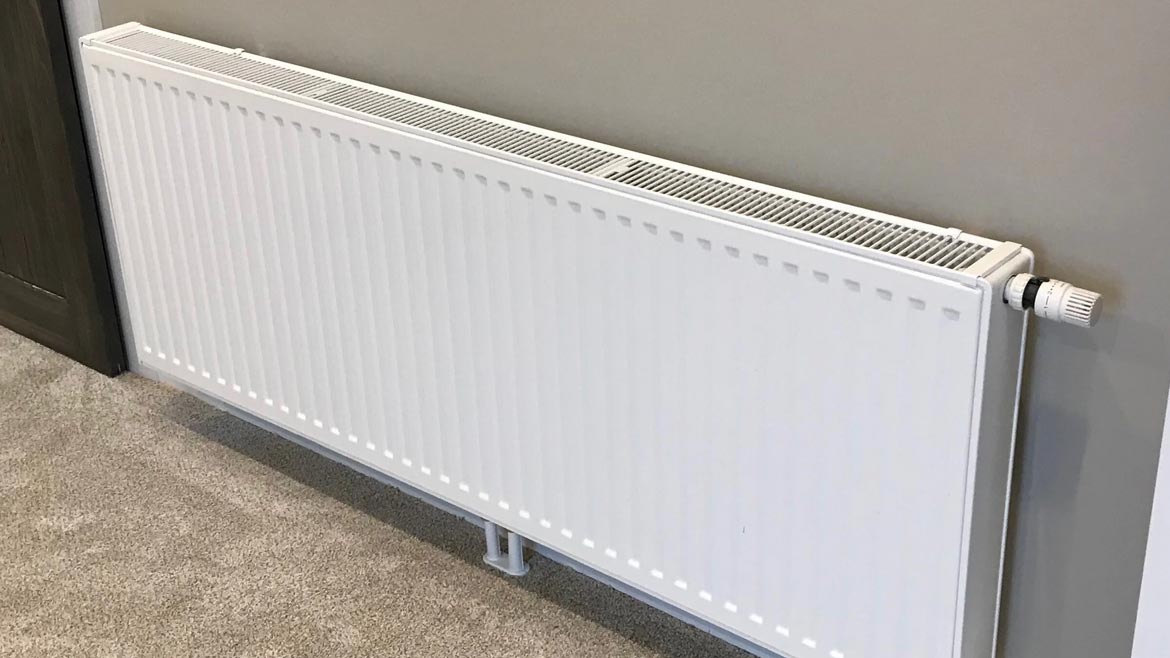
Figure 4 Image courtesy of John Siegenthaler P.E.
Any of these heat emitter options can also be combined into a single system, depending on rooms space, finishes, aesthetic preferences, etc. I recommend designing any combination of these heat emitters around a single supply water temperature to eliminate the need for mixing. Keep the supply water temperature under design load conditions no higher than 120 ºF.
Acquire advocates
It has been my experience that several demographics of building professionals have a curiosity about modern hydronics, but simply don’t know enough to embrace its use. These includes architects, home energy auditors, weatherization pros, government energy planners, and builders specializing in low energy home construction.
These professionals are highly motivated by energy efficiency, carbon reduction, resilient design, and reduced use (or even elimination) of fossil fuels. Our industry needs to show them how these objectives can be met using hydronics technology.
The goal is not to convert them into designers or installers of hydronic systems. Rather it’s to convince them that hydronic systems have the flexibility to adapt to the needs of the buildings they work with. As advocates, and often the first professionals to interact with building owners seeking more efficient solutions for HVAC, they can communicate the benefits of hydronic systems to people, who might otherwise never visit your showroom or other places of business.
Many of these building pros think of air-to-air heat pumps (ducted or mini-splits) as the go-to solution for heating and cooling in any low-load home. Their default solution often combines an air-to-air heat pump for heating and cooling with a heat pump water heater and a heat recovery ventilator (HRV). We need to show them how a hydronic system using a heat pump as its primary heat source can provide heating, cooling, domestic hot water, and integrate with heat recovery ventilation.
To follow up on this concept, I suggest that those selling hydronic-based systems also consider learning about and eventually selling a line of heat recovery ventilators (HRVs) and/or energy recovery ventilators (ERVs). In Canada these ventilation systems are either highly recommended, or in some provinces mandatory, for new home construction. It’s quite possible that such requirements will soon be parts of our model codes. Will you be ready with solutions?
Double duty ducts
When a hydronic air handler and its associated ducting will be used to distribute cool / dry air from a chilled water system, that same ducting can be used to distribute fresh air from a heat recovery ventilator. One duct system can handle both needs, eliminating the expense of separate ducting for the heat recovery ventilator.
In very cold climates the air handler coil that cools and dehumidifies air in summer can also partially heat ventilation air in winter. For example, an HRV with a typical recovery efficiency of 70% will only heat air coming in at -10 ºF to about 46 ºF. Although that air can be carefully delivered through ceiling diffusers that mix it with room air, using the air handler to boost it’s temperature to around 70 ºF will help prevent perceived drafts. If you do this be sure to use an antifreeze solution in the coil.
Beyond the heat source
Want more reasons to convince energy-minded building pros that modern hydronics technology aligns with their goals? Lead them into a discussion on distribution efficiency. The ability of water to carry heating and cooling energy through a building using less than 10 percent of the electrical energy required by a best-in-class forced air distribution system of equal thermal capacity.
I’ve designed hydronic systems that can deliver 36,000 Btu/hr using a single circulator operating at 44 watts under design load conditions. That equates to distribution efficiency of 36,000 / 44 = 818 Btu/hr/watt. No forced-air distribution system of equivalent thermal capacity even comes close to that efficiency. It’s analogous to converting all the light bulbs in a house from incandescent to LED.
The vast majority of energy professionals outside of the hydronics industry have never heard of distribution efficiency. Still, I’ve seen a lot of interest from these pros when an opportunity to present the concept arises. Bring it up and have hardware and design concepts ready to blow away the efficiency of forced air heating.
Tiny tubes
Space and aesthetics matter to building pros as well as most consumers. They don’t like to give up space for mechanical systems, and they don’t want to see any more of those systems than absolutely necessary.
So show them how the physical properties of water versus those of air allow a 1/2 inch PEX tube to carry as much heating or cooling effect as a 9 inch round duct or 7x10 rectangular duct, as shown, to scale, in figure 5.
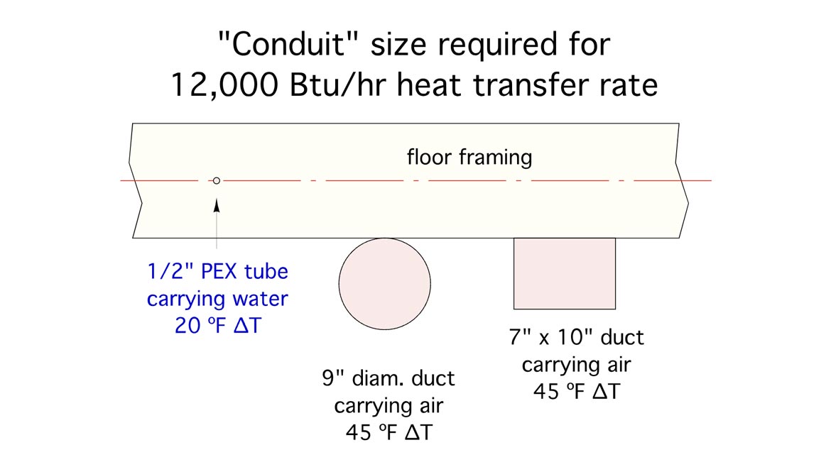
Figure 5 Image courtesy of John Siegenthaler P.E.
Ask them if they would rather install the thermal transport hardware shown in figure 6a or 6b?
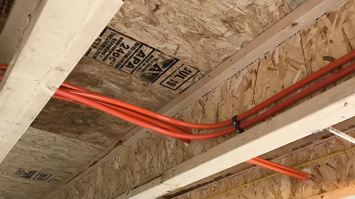
Figure 6a
Figure 6b Images courtesy of John Siegenthaler P.E.
Hydronics rediscovered
It’s good to periodically pause and think critically about what you do, how passionate you are about it, and how you explain it to others. Perhaps what you’ve just read will help with that. I also hope you’re encouraged by some of the opportunities we’ve discussed, and ready to leverage the technical merits of modern hydronics, with market trends that set the stage for its use. There’s a lot of “low hanging fruit” out there just waiting to be picked.
I’ll close with a more uplifting elevator speech: Hydronic systems use water rather than air for moving heating and cooling energy through buildings. They do this using far less electricity compared to forced-air systems, and while providing superior comfort. Hardware is readily available to leverage these advantages while remaining compatible with rapidly changing fuel options. The possibilities of how modern hydronics technology can be applied are virtually unlimited. Would you be interested in learning more?
Looking for a reprint of this article?
From high-res PDFs to custom plaques, order your copy today!


