Geothermal heat pump systems with manifolded earth loops may offer many advantages
Less time in the trenches.

Figure 1. Photo courtesy of Larry Wurtak.

Figure 2.


Figure 4. Photo courtesy of REHAU.

Figure 5. Photo courtesy of Caleffi.

Figure 6. Photo courtesy of REHAU.

Figure 7.

Figure 8. Photo courtesy of Harvey Youker.

Figure 9.

Figure 10.


Most residential geothermal heat pump systems use closed-earth heat exchangers constructed of high-density polyethylene tubing. The overall earth heat exchanger usually consists of several parallel piping circuits joined into a set of headers.
In systems using horizontal earth heat exchangers, the header system usually is fabricated in the trench and the entire piping assembly is buried several feet below the surface. Figure 1 (see above) shows an example where six “slinky-” style earth loop circuits have been joined to reverse return headers (seen near the bottom center of the photo).
In systems using vertical earth heat exchangers, individual earth loop circuits are inserted and grouted into boreholes. These circuits are then joined into a common set of headers as illustrated in Figure 2. The headers usually are configured for reverse return flow and have incrementally stepped pipe sizes between the individual circuit connection tees. These details help equalize flow rates among the individual circuits, assuming the individual earth loop circuits are the same length.
The two most-widely accepted methods of joining HPDE pipe for geothermal earth loops are butt fusion and socket fusion.
A butt-fusion joint is made by heating the ends of polyethylene tubing to about 500º F for a prescribed time (usually 30 seconds to a minute depending on pipe size) and then pressing the semi-molten ends together using a special jig. Figure 3 shows the resulting “double rollback bead” joint formed during butt fusion. This joint, when properly done, is stronger than the pipe itself.
Socket fusion involves joining pipe with fittings. The inside of the fitting socket and the outside diameter of the tubing are simultaneously heated using a special tool. Once these surfaces are semi-molten, the pipe and fitting are pulled off the heating tool and pushed together without twisting. Again, the result is an extremely strong and permanent joint.
The reliability of properly done fusion joints has helped bolster the market for geothermal heat pump systems. Still, fusion joining requires proper tooling and technique. A set of tooling to create butt-fusion joints, socket-fusion joints and saddle tees in pipes up to 2-in. size can cost several thousand dollars.
Although “trench-based” earth heat exchanger fabrication using fusion joining has been successfully used on thousands of installations, it does, at times, have to be performed under less than ideal conditions, as shown in Figure 4.
Working with fusion equipment under cold, wet and muddy conditions requires special care to ensure the joints being made are clean, dry and properly heated.
Get it together
So what are the alternatives to fusion joints, and site-fabricated/buried headers?
One relatively new option that has made its way from Europe to North America is the geothermal manifold. In some respects, this approach is similar to routing multiple radiant panel heating circuits to a common manifold station. However, geothermal manifolds typically are larger in diameter to accommodate higher flow rates. Most are built of polymer materials that easily can withstand the relatively low operating temperature and pressure range of earth loops.
Figure 5shows an example of a modular geothermal manifold assembly. It is assembled by sliding the desired number of tubing connectors onto a common set of tie rods that fasten to matching end assemblies.
The basic geothermal manifold assembly shown in Figure 5 can be “trimmed out” in several ways. The simplest is to just add adapters that allow the individual earth loop circuits to be connected to the manifolds. The next step would be to add ball valves on each connection. This allows each earth loop circuit to be isolated when necessary. This is particularly helpful when filling and purging the overall earth heat exchanger. Another possibility is to add flow meters to each manifold connection. These can be used to verify proper flow. They also can be used in combination with temperature measurement to estimate the rate of heat transfer from each circuit.
Figure 6shows another example of a geothermal manifold. In this case, the manifold body is built of heat-fused polypropylene pipe and fitted with brass isolation valves and a flow meter for each circuit. The earth loop circuits are crosslinked polyethylene piping.
The benefits
The use of manifold-based earth loops provides several advantages relative to earth loops created using buried fusion joints. These include:
• The possibility for installing several different earth loop configurations without need of fusion joints, and thus no need of fusion equipment. This is a significant advantage for contractors who do an occasional geothermal heat pump installation, but can’t justify buying all the tooling required for fusion joints.
• Eliminating the need of reverse return piping and stepped pipe sizes in site-build (buried) headers to help balance flows through each earth loop circuit. This simplifies and speeds installation.
When the manifold station includes isolation and flow indicating / balancing valves, additional advantages include:
• Each circuit ofthe earth loop can be independently flushed during filling and purging. This significantly reduces the size of the flush pump required to fill and purge the system.
• The flow rate through each earth loop circuit can be verified and adjusted if necessary.
• If a buried circuit ever fails due to future excavation, drilling, etc., it can be completely isolated at the manifold.
Inside or outside
Geothermal manifold stations can be located either inside or outside the building served by the heat pump.
Figure 7illustrates how individual earth loop circuits can pass through a basement wall and connect to a geothermal manifold. 90º compression elbows are used to change the direction of the piping penetrating the wall from horizontal to vertical under the manifold.
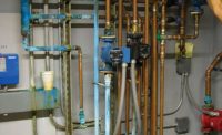
Figure 8shows a neatly installed geothermal manifold mounted adjacent to the water-to-water heat pump it supplies. Notice that the earth loop is equipped with both an air separator and dirt separator. It also is equipped with a diaphragm-type expansion tank that limits seasonal pressure variation within the earth loop.
Several options exist for geothermal manifold stations located outside the building. One is to construct a manifold pit using precast concrete pipe or a rectangular concrete vault. Such a pit should be designed as either watertight or bottom-drained.
A watertight manifold pipe requires compression seals at all piping penetrations, as well as a watertight lid. The goal is to prevent entry of ground or surface water. Figure 9 shows an example of a water-tight manifold pit with a sealed cover plate. The design assumes an installation in a relatively cold winter climate, thus the tubing enters through the sidewall of the pit several feet below the surface. The upper walls and cover of the pit are insulated with extruded polystyrene to reduce heat losses.
A bottom-drained manifold pit usually has crushed stone and drainage piping at its bottom to prevent water accumulation.
Pleasant purging
One of the biggest advantages of using valved manifold-based earth heat exchangers is in the size of the pump required for filling and purging. That pump will be significantly smaller for a valved, manifolded system because each earth parallel circuit can be individually flushed. Without valves, all the circuits must be flushed simultaneously.
Purging requires a minimum flow velocity of 2 ft. per second in every tube that’s being purged at a given time. That flow velocity corresponds to a flow rate of 3.6 gpm in a 3/4-in. DR-11 HDPE tube, and 5.6 gpm in a DR-11 HDPE tube.
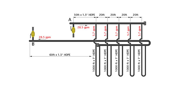
Here’s a comparison of the flow rates and corresponding head losses required for purging a conventional earth loop vs. one using a valved manifold.
Based on working through a few calculations, the non-valved earth loop circuit shown in Figure 10 requires a purging pump capable of producing a minimum flow rate of 28.5 gpm at a corresponding head of 72.6 ft. That’s a substantial pump, likely in the range of 1.5-2-horsepower and also likely to require 240 VAC power.
By comparison, if the same set of five 1,000-ft. parallel piping circuits were connected to a valved manifold and purged one at a time, the purging pump would only have to deliver a flow rate of 5.7 gpm with corresponding head loss of 20.7 ft. This is within the performance range of a portable submersible pump that operates on 120 VAC.
If you’re involved with geothermal heat pumps, I urge you to consider use of manifolded earth loops. They offer several unique benefits, not the least of which is less time in the trenches.
HELPFUL LINKS:
Looking for a reprint of this article?
From high-res PDFs to custom plaques, order your copy today!


